Inhero MR2
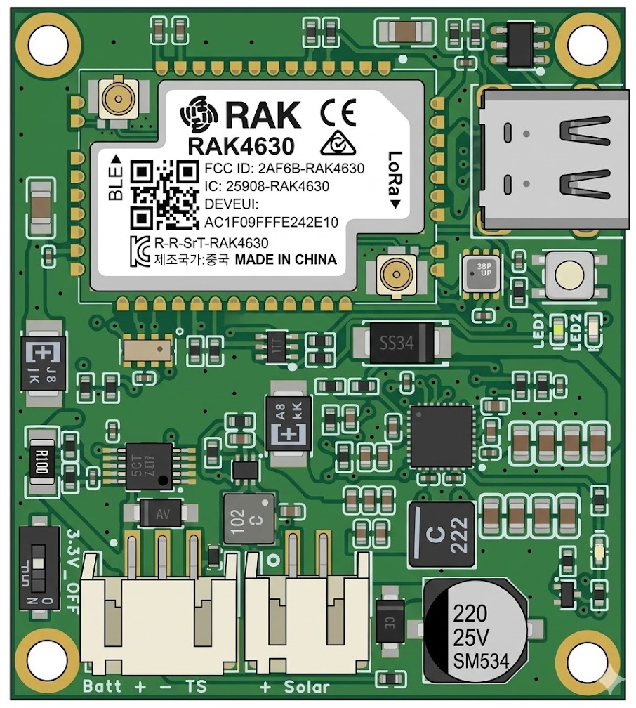
Table of Contents
- Overview
- Current Feature Matrix
- Power Management Features
- Firmware Build
- CLI Commands
- Diagnostics & Troubleshooting
- Regulatory Notes & CE Compliance
- See Also
Overview
The Inhero MR2 is an application-specific hardware platform for the autonomous, long-term operation of mesh infrastructure at hard-to-reach locations. Active idle consumption is 6.0 mA at 4.2 V and 7.7 mA at 3.3 V (USB off, no radio TX), which gives a full-featured repeater long battery life from a compact cell and a small solar panel. A universal solar input with active MPPT harvests over a wide input range, so a compact, low-profile installation is usually enough and the peripherals need no over-dimensioning. Li-ion, LiFePO4, LTO and Na-ion batteries are supported natively, and RTC-based recovery brings the board back on its own after a low-voltage shutdown, so an empty battery does not force a site visit. This lowers long-term operating costs at sites where a manual service visit is expensive because the location is hard to reach.
Hardware Version: Rev 1.1
Key Features:
- Core: Based on RAK4630(H) (nRF52840 + SX1262) — high-band variant covering IN865, EU868, US915, AU915, KR920 and AS923. The low-band variant RAK4630(L) (EU433 / CN470) is not fitted, so 433 MHz / 470 MHz operation is not possible. See DATASHEET.md — LoRa Frequency Bands.
- Power Path: BQ25798 Buck/Boost Charger. Enables energy harvesting even when solar voltage is below battery voltage (critical for low-light conditions).
- High-Efficiency Rail: 3.3V rail via TPS62840 for maximum efficiency.
- Robust Monitoring: INA228 Coulomb Counter for precise SOC tracking (essential for LiFePO4 chemistry) and long-term energy statistics.
- Universal Solar Input: 3.6V – 24V with autonomous MPPT tracking and integrated protection against "stuck states" (hardware watchdog logic).
- Environmental Sensing & Timekeeping: Integrated BME280 and RV-3028 RTC for autonomous wake-up management and precise time base. See FAQ #23 for why a correct clock matters.
- Form Factor: Only 45 × 40 mm – optimized for low-profile enclosures and minimal mechanical stress.
⚠ WARNING — No Reverse Polarity Protection: The board has no hardware reverse polarity protection on the battery or solar input. Connecting with reversed polarity will cause immediate, irreversible damage. Always verify correct polarity before connecting any power source.
Current Feature Matrix
| Feature | Status | Notes |
|---|---|---|
| INA228 ALERT → Low-Voltage System Sleep | Active | ISR on P1.02 → volatile flag → tickPeriodic() → System Sleep with GPIO latch + RTC Wake |
| RTC Wakeup (Low-Voltage Recovery) | Active | 60 min (periodic) |
| BQ CE Pin Safety (FET-inverted) | Active | GPIO HIGH → FET ON → CE LOW → charge ON (BQ25798 CE active-low), Dual-Layer: GPIO + I2C |
| System Sleep with latched CE | Active | < 500µA, GPIO4 latch preserved HIGH → FET ON → CE LOW → solar charging possible |
| SOC 0% after Low-Voltage Recovery | Active | SOC initialized to 0% on recovery, auto-sync on "Charging Done" |
| SOC via INA228 + manual battery capacity | Active | set board.batcap available |
| SOC→Li-ion mV Mapping (workaround) | Active | Will be removed when MeshCore transmits SOC% natively |
| MPPT Recovery + Stuck-PGOOD Handling | Active | Cooldown logic active |
| PFM Forward Mode | Active (chip default) | Enabled by BQ25798 power-on default (PFM_FWD_DIS=0, REG0x12); the firmware does not modify it. Improves efficiency at low solar currents |
JEITA override (set board.jeitaignore) |
Available, off by default | Li-ion 1S / LiFePO4 1S only; becomes active while board.batcap is set and board.imax is at or below 0.05C |
Power Management Features
Low-Voltage Handling (Flag/Tick Architecture)
- INA228 ALERT fires at
lowv_sleep_mv(hardware interrupt on P1.02) - ISR sets
lowVoltageAlertFired = true(volatile flag only, no FreeRTOS call) tickPeriodic()(main loop, nexttick()) checks flag → shutdown:- CE pin → HIGH (FET ON → CE LOW → charging active)
- P0.04 excluded from
disconnectLeakyPullups()→ GPIO latch preserved in sleep - RTC wake configured (
LOW_VOLTAGE_SLEEP_MINUTES= 60 min) sd_power_system_off()→ System Sleep with GPIO latch (< 500µA)- RTC Wake (hourly) → system boots, early-boot checks VBAT:
- Below
lowv_wake_mv→ immediately back to System Sleep (CE remains latched LOW) - Above
lowv_wake_mv→ normal boot, SOC starts at 0%
Note: All I2C operations (MPPT, SOC, Hourly Stats) run in main loop context via
tickPeriodic()— no FreeRTOS tasks for I2C, no mutex needed.
BQ CE Pin (Rev 1.1 — FET-inverted)
- CE N-FET: Gate ← GPIO4 (ext. pull-down), Drain → CE, Source → GND
- GPIO HIGH → FET ON → CE LOW → charging ON (BQ25798 CE active-low)
- GPIO LOW / High-Z → ext. pull-down on gate → FET OFF → pull-up on CE → CE HIGH → charging OFF
- System Sleep: GPIO4 latch preserved HIGH (excluded from
disconnectLeakyPullups()) → FET ON → CE LOW → solar charging active - Safety default: RAK unpowered/unflashed → pull-down on gate → FET OFF → CE HIGH → charging disabled
- Dual-Layer: CE pin (hardware FET) +
setChargeEnable()(I2C register)
Voltage Thresholds (all chemistries)
| Chemistry | lowv_sleep_mv | lowv_wake_mv | Hysteresis |
|---|---|---|---|
| Li-ion 1S | 3100 | 3300 | 200mV |
| LiFePO4 1S | 2700 | 2900 | 200mV |
| LTO 2S | 3900 | 4100 | 200mV |
| Na-ion 1S | 2500 | 2700 | 200mV |
- lowv_sleep_mv: INA228 ALERT threshold → triggers System Sleep with GPIO latch
- lowv_wake_mv: RTC wake threshold → boot only when VBAT is above, also 0% SOC marker
System Sleep Power Consumption
- < 500µA total consumption (nRF52840 System-Off + RTC + quiescent currents of all components)
- GPIO4 latch preserved HIGH → FET ON → CE LOW → solar charging active
Active Idle Power Consumption
- 6.0 mA @ VBAT 4.2 V (USB off, no radio TX)
- 7.7 mA @ VBAT 3.3 V (USB off, no radio TX)
- +0.8–1.0 mA with USB peripheral enabled
- USB is auto-managed: enabled on VBUS detect, disabled on removal
Power Saving Measures
- WFE Idle (
board.sleep(0)): CPU enters Wait-For-Event between loop iterations. Wakes on any interrupt (radio, SysTick, USB, I2C) — typically within 1 ms. Reduces nRF52840 CPU current from ~3 mA (busy-loop) to ~0.5–0.8 mA. - USB Auto-Disable: nRF52840 USB peripheral is automatically disabled when no VBUS is detected, saving ~0.8–1.0 mA. Re-enabled automatically when USB cable is connected.
Coulomb Counter & SOC Tracking
- Real-time SOC tracking via INA228 (±0.1% accuracy)
- 100mΩ shunt resistor (1.6A max current)
- 200mV uniform hysteresis for all chemistries (lowv_sleep_mv → lowv_wake_mv)
- Manual capacity:
set board.batcapfor fixed capacity
SOC→Li-ion mV Mapping (Workaround)
- Problem: MeshCore only transmits
getBattMilliVolts(), not SOC%. The MeshCore app uses a Li-ion curve for SOC calculation — incorrect display for LiFePO4/LTO. - Solution: When valid coulomb-counting SOC is available, an equivalent Li-ion 1S OCV (3000–4200 mV) is returned, so the app displays the correct SOC%. See TELEMETRY.md for details on how this affects the app display.
- This workaround will be removed once MeshCore supports native SOC% transmission.
- → FAQ #11 — SOC shows 0% or N/A?
Batt-TTL Prediction
Batt-TTL is short for battery time-to-live — the estimated remaining runtime on battery. It is not the packet hop limit that "TTL" denotes in mesh networking. - Time base: 7-day moving average (
avg_7day_daily_net_mah) of daily net energy consumption - Data source: 168-hour ring buffer (7 days) with hourly INA228 coulomb counter samples (charged/discharged/solar mAh) - Formula:TTL_hours = max(0, SOC% × capacity_mah / 100 − capacity_mah × (1 − f(T))) / |avg_7day_daily_net_mah| × 24- f(T): Cold-temperature derating factor (trapped-charge model) — at low temperatures part of the stored charge is unusable and is subtracted first; f(T) = 1 at warm temperatures - Prerequisites:living_on_battery == true(24h deficit), min. 24h data, capacity known - Batt-TTL = 0: Solar surplus, no 24h data available, or capacity unknown - CLI: Batt-TTL is shown inget board.stats(BAT mode only, e.g.BT:12d0h) - Telemetry: Transmitted as days via CayenneLPP Distance field (max. 990 days for "infinite"). See TELEMETRY.md for channel details.
Solar Power Management
- Solar current display: The BQ25798 IBUS ADC is inaccurate at low currents (~±30mA error). Therefore solar current is displayed in steps:
0mA— ADC reports exactly 0 (no solar current)<50mA— 1–49mA (ADC unreliable in this range)~72mA— 50–100mA with rounding symbol~(limited accuracy)385mA— >100mA without rounding symbol (sufficiently accurate)- Always integer without decimal places (no pseudo-precision)
- PFM Forward Mode: PFM forward mode is enabled by BQ25798 power-on default (PFM_FWD_DIS=0, REG0x12); the firmware does not modify it. Improves efficiency at low currents.
- MPPT VOC_PCT 81.25%: The BQ25798 MPPT is configured to VOC_PCT=81.25% (instead of the chip default 87.5%). This value matches the typical Vmp/Voc ratio of crystalline silicon solar cells (~80-83%).
- MPPT Recovery: Re-enables MPPT on PowerGood=1 (readback check: only on actual change)
- BQ INT pin not used: No interrupt — pure polling every 60s in
runMpptCycle() - Error monitoring: Diagnostic commands show FAULT_STATUS registers (0x20, 0x21) for detailed analysis incl. VBAT_OVP, VBUS_OVP and temperature conditions
- VREG display: Shows the actually configured battery regulation voltage in diagnostics for threshold verification
JEITA Temperature Zone Configuration
The BQ25798 uses the TS pin (NTC thermistor) for JEITA-compliant temperature-dependent charge control. The Inhero MR2 uses a voltage divider (RT1=5.6 kΩ pullup to REGN, RT2=27 kΩ parallel to GND) that shifts TS thresholds lower than the TI reference design (5.24 kΩ / 30.31 kΩ). The shift is temperature-dependent: ~5–6 °C in the cold range, ~2–3 °C in the warm/hot range (because at low temperatures the NTC resistance is large relative to RT2, amplifying the divider mismatch).
| JEITA Zone | BQ25798 Threshold | TI Reference | Inhero MR2 (actual) | Shift | Firmware Config |
|---|---|---|---|---|---|
| T-Cold (charge suspend) | VT1 = 72.0% REGN | +3.7 °C | −2.0 °C | −5.7 °C | threshold fixed |
| T-Cool (reduced current) | VT2 = 69.8% REGN | +7.9 °C | +2.8 °C | −5.1 °C | set board.fmax |
| T-Warm start | VT3 = 37.7% REGN | +54.5 °C | +52.2 °C | −2.3 °C | TS_WARM = 55°C register setting |
| T-Hot (charge suspend) | VT5 = 34.2% REGN | +59.9 °C | +57.7 °C | −2.2 °C | threshold fixed |
While the JEITA override is active, TS_IGNORE = 1 forces all four TS status bits to 000: every zone in this table is bypassed, and the
board.fmaxreduction is inert.Calculation based on: NTC 103AT (B25/50=3435) for TI reference, NCP15XH103F03RC (B25/85=3380) for Inhero. Typical %REGN values from BQ25798 datasheet.
Key firmware settings in configureBaseBQ():
TS_WARM = 55°C(BQ register value): Moves the WARM zone threshold from the default 45 °C setting (44.8% REGN, ~41.8 °C with Inhero divider) up to 37.7% REGN (~52.2 °C with Inhero divider). This prevents premature WARM zone entry at moderate temperatures.JEITA_VSET = UNCHANGED: No battery regulation voltage reduction in the WARM zone. The POR default (VREG−400 mV) would reduce VREG to 3.1 V for LiFePO4, causing VBAT_OVP at normal battery voltages (3.3–3.5 V).JEITA_ISETH = ICHG unchanged(POR default, retained): No charge current reduction in the WARM zone. Combined with JEITA_VSET=UNCHANGED, the WARM zone is effectively neutralized — charging continues at full voltage and full current.AUTO_IBATDIS = disabled: Disables the BQ25798's automatic 30 mA battery discharge during VBAT_OVP. The POR default actively drains the battery at ~30 mA (IBAT_LOAD) when OVP is triggered, which is counterproductive for solar-powered systems.
Background: With default BQ25798 settings, the combination of the Inhero divider offset and LiFePO4 chemistry caused a failure chain at ~42 °C: WARM zone entry → VREG reduced to 3.1 V → VBAT_OVP (battery at 3.47 V > 104% × 3.1 V) → active 30 mA discharge → net −45 mA drain despite solar input. The settings above prevent this entirely. The WARM zone (52–58 °C with Inhero divider) now has no effect on charging behavior.
JEITA override (set board.jeitaignore)
set board.jeitaignore 1 sets the BQ25798 TS_IGNORE bit (NTC Control 1, register 0x18, bit 0). The charger then treats the TS pin as always good for charging, so charging continues below the T-Cold threshold. Off by default.
- Chemistry: accepted for Li-ion 1S and LiFePO4 1S. LTO 2S and Na-ion 1S need no JEITA supervision (
needs_jeita = falsein the chemistry table) and run with TS_IGNORE set anyway; for them the verb answersErr: This chemistry runs without JEITA (always 1). - Gate: the override becomes active only while
board.batcaphas been written explicitly andboard.imaxis at or below 0.05C of that capacity. Writes toimaxorbatcapre-derive the state, and the reply names the change. - Stored as a wish: the flag is kept in NVS, the effective state is derived on every chemistry apply and is never persisted. A failing gate does not discard the flag — the override re-arms on its own once
imax/batcappass again. From power-on until the stored configuration is applied, TS_IGNORE is cleared and the hardware temperature guard is in charge. - Scope of the switch: with TS_IGNORE set, all four TS status bits report 000, so the charge suspend at T-Hot (~+57.7 °C with the Inhero divider) is disabled as well. The firmware offers no replacement for either limit — the board sleeps in SYSTEMOFF with the charger enabled and no control loop runs there, so the 0.05C bound is the whole safety argument.
- Risk: charging Li-ion or LiFePO4 in frost is at the operator's own risk. The 0.05C bound limits the rate; lithium plating on the graphite anode stays cumulative and permanent, and it shows up as capacity quietly gone. See BATTERY_GUIDE.md for the field evidence, the temperature scope and the full trade.
Firmware Build
# Repeater (default)
platformio run -e Inhero_MR2_repeater

# Repeater with RS232 bridge (Serial2 on P0.19/P0.20)
platformio run -e Inhero_MR2_repeater_bridge_rs232

# Sensor
platformio run -e Inhero_MR2_sensor
CLI Commands
Get Commands
get board.bat       # Query current battery type
                    # Output: liion1s | lifepo1s | lto2s | naion1s | none

get board.fmax      # Query frost charge behavior
                    # Output: 0% | 20% | 40% | 100%
                    # Value = max charge current in T-Cool range
                    # (approx. -2 °C to +3 °C, see JEITA table in README),
                    # relative to board.imax
                    # 40% at imax=500mA → max. 200mA charge current in T-Cool range
                    # 0% = charging blocked in T-Cool range
                    # 100% = no reduction (full current even in cold)
                    # Below approx. -2 °C (T-Cold): charging blocked (JEITA),
                    # unless the JEITA override is active — see
                    # set board.jeitaignore
                    # Note: Only charging is restricted. With sufficient
                    # solar, the board continues to run on solar power —
                    # the battery is neither charged nor discharged.
                    # Output is N/A while the JEITA override is active:
                    # chemistries that run without JEITA (LTO / Na-ion /
                    # none), or an armed set board.jeitaignore

get board.imax      # Query maximum charge current
                    # Output: <current>mA (e.g. 200mA)

get board.mppt      # Query MPPT status
                    # Output: MPPT=1 (enabled) | MPPT=0 (disabled)

get board.altitude  # Query installation altitude for BME280 QNH correction
                    # Output: <metres> m or N/A (station pressure)

get board.telem     # Query real-time telemetry with SOC
                    # Output: B:<V>V/<I>mA/<T>C SOC:<percent>% S:<V>V/<solar current>
                    # Examples:
                    #   B:3.85V/125.4mA/22C SOC:68.5% S:5.12V/385mA      (>100mA: accurate)
                    #   B:3.85V/-8.2mA/18C SOC:72.0% S:4.90V/~72mA      (50-100mA: ~estimate)
                    #   B:3.30V/-45.0mA/5C SOC:40.1% S:0.00V/<50mA      (<50mA: ADC inaccurate)
                    # Output variants:
                    # - SOC:N/A — no valid coulomb-counting SOC available
                    # - SOC:68.5% (52%) — second value = cold-derated SOC,
                    #   shown when the temperature derating factor is < 1
                    # - <T>C becomes N/A when the NTC temperature is unavailable
                    # Components:
                    # - B: Battery (Voltage/Current/Temperature/SOC)
                    # - S: Solar (Voltage/Current — accuracy depends on BQ25798 IBUS ADC)

get board.stats     # Query energy statistics (balance + MPPT)
                    # Output: <24h>/<3d>/<7d>mAh C:<24h> D:<24h> 3C:<3d> 3D:<3d> 7C:<7d> 7D:<7d> <SOL|BAT> M:<mppt>% BT:<ttl>
                    # Example: +125/+45/+38mAh C:200 D:75 3C:150 3D:105 7C:140 7D:102 SOL M:85% BT:N/A
                    # Example: -30/-45/-40mAh C:10 D:40 3C:5 3D:50 7C:8 7D:48 BAT M:45% BT:72h
                    # Components:
                    # - +125: Last 24h net balance (charge - discharge) in mAh
                    # - +45: 3-day average net balance in mAh
                    # - +38: 7-day average net balance in mAh
                    # - C/D: Charged/Discharged mAh (24h)
                    # - 3C/3D: 3-day average charged/discharged mAh
                    # - 7C/7D: 7-day average charged/discharged mAh
                    # - SOL: Running on solar (self-sufficient)
                    # - BAT: Living on battery (deficit mode)
                    # - M:85%: MPPT enabled percentage (7-day average)
                    # - BT:72h: Batt-TTL (only shown if BAT mode, 7d-avg basis)
                    #   Format: BT:12d5h (≥24h) or BT:72h (<24h) or BT:N/A

get board.cinfo     # Charger info + last PG-stuck HIZ toggle
                    # Output: <state> + flags
                    # States: !CHG, PRE, CC, CV, TRICKLE, TOP, DONE

get board.selftest  # I²C hardware probe (all on-board devices)
                    # Output: INA:<state> BQ:<state> RTC:<state> BME:<state>
                    # States: OK | NACK | WR_FAIL (RTC only, write-verify mismatch)

get board.conf      # Query all configuration values
                    # Output: B:<bat> F:<fmax> M:<mppt> I:<imax> Vco:<voltage> V0:<0%SOC>
                    # F: reads N/A while the JEITA override is active
                    # A trailing J:1 is appended while the user override is
                    # armed (Li-ion / LiFePO4 only)

get board.batcap    # Query battery capacity
                    # Output: <capacity> mAh (set) or <capacity> mAh (default)
                    # Shows whether capacity was manually set or chemistry default

get board.tccal     # Query NTC temperature calibration offset
                    # Output: TC offset: <+/-offset> C (0.00=default)

get board.leds      # Query LED enable status
                    # Output: "LEDs: ON (Heartbeat + BQ Stat)" or "LEDs: OFF (Heartbeat + BQ Stat)"
                    # Shows whether heartbeat LED and BQ25798 stat LED are enabled

get board.jeitaignore  # Query JEITA override state
                       # Output: jeitaignore 0
                       #   → override off
                       # Output: jeitaignore 1
                       #   → override active
                       # Output: jeitaignore 1 (chemistry)
                       #   → LTO / Na-ion run without JEITA
                       # Output: jeitaignore 1, N/A, C>0.05
                       #   → flag stored, imax above 0.05C of batcap
                       # Output: jeitaignore 1, N/A, batcap not set
                       #   → flag stored, batcap never written
Set Commands
set board.bat <type>           # Set battery type
                               # Options: lto2s | lifepo1s | liion1s | naion1s | none
                               # none = no battery / unknown (charging disabled)

set board.fmax <behavior>      # Set frost charge behavior
                               # Options: 0% | 20% | 40% | 100%
                               # Limits charge current in T-Cool range
                               # (approx. -2 °C to +3 °C, see JEITA table in README)
                               # to X% of board.imax
                               # 0% = charging blocked in T-Cool range
                               # 20% = max. 20% of imax in T-Cool range
                               # 40% = max. 40% of imax in T-Cool range
                               # 100% = no reduction
                               # Below approx. -2 °C (T-Cold): charging blocked
                               # (JEITA), unless the JEITA override is active —
                               # see set board.jeitaignore
                               # Note: Only charging is restricted. With sufficient
                               # solar, the board continues to run on solar power —
                               # the battery is neither charged nor discharged.
                               # Refused for chemistries that run without JEITA
                               # (LTO / Na-ion):
                               #   Err: Fmax setting N/A for this chemistry (JEITA disabled)
                               # Refused while the override is active:
                               #   Err: Fmax N/A while jeitaignore is on

set board.imax <current>       # Set maximum charge current in mA
                               # Range: 50-1500mA (BQ25798 minimum: 50mA)
                               # imax is part of the jeitaignore gate: when the
                               # write changes the override state, the reply gains
                               # "; jeitaignore 1" or "; jeitaignore N/A, C>0.05"

set board.mppt <1|0>           # Enable/disable MPPT
                               # 1 = enabled, 0 = disabled

set board.altitude <metres>    # Store installation altitude (-500 to 9000 m)
                               # BME280 pressure is then reported as QNH
set board.altitude clear       # Remove altitude; report station pressure again

set board.batcap <capacity>    # Set battery capacity in mAh
                               # Range: 100-100000 mAh
                               # Used for accurate SOC calculation
                               # batcap is part of the jeitaignore gate: when the
                               # write changes the override state, the reply gains
                               # "; jeitaignore 1" or "; jeitaignore N/A, C>0.05"

set board.tccal                # Calibrate NTC temperature
                               # Two modes:
                               # 1) set board.tccal         → auto-calibration via BME280
                               #    Output: TC auto-cal: BME=<temp> offset=<+/-offset> C
                               # 2) set board.tccal reset   → reset offset to 0.00
                               #    Output: TC calibration reset to 0.00 (default)

set board.leds <on|off>        # Enable/disable heartbeat + BQ stat LED
                               # on/1 = enable, off/0 = disable
                               # Boot LEDs follow this setting; only the
                               # low-voltage recovery flash (3 blue blinks)
                               # is always active

set board.soc <percent>        # Manually set SOC
                               # Range: 0-100
                               # Note: INA228 must be initialized

set board.jeitaignore <1|0>    # Allow charging below the JEITA T-Cold threshold
                               # 1 = charger ignores the TS pin (TS_IGNORE)
                               # 0 = JEITA temperature control active (default)
                               # Li-ion 1S / LiFePO4 1S only. LTO / Na-ion:
                               #   Err: This chemistry runs without JEITA (always 1)
                               # Gate: board.batcap must be set explicitly and
                               # board.imax must be at or below 0.05C of it
                               # Replies: jeitaignore set to 1
                               #          jeitaignore set to 1, N/A, C>0.05
                               #          jeitaignore set to 1, N/A, batcap not set
                               #          jeitaignore set to 0
                               # The flag stays stored when the gate fails and
                               # re-arms once imax/batcap pass again
                               # The override also drops the hot-side charge
                               # suspend (~ +57.7 °C). Charging Li-ion or LiFePO4
                               # in frost is at the operator's own risk —
                               # see BATTERY_GUIDE.md
Diagnostics & Troubleshooting
I²C Hardware Self-Test
get board.selftest
Probes all I²C devices on the board and reports their status in one line:
INA:OK BQ:OK RTC:OK BME:OK
| Device | Address | Test |
|---|---|---|
INA |
0x40 |
INA228 power monitor — address ACK |
BQ |
0x6B |
BQ25798 charger — address ACK |
RTC |
0x52 |
RV-3028 RTC — address ACK plus user-RAM (0x1F) write/readback verification with two patterns (0xA5, 0x5A); original byte is restored |
BME |
0x76 |
BME280 environment sensor — address ACK |
Possible per-device states:
OK— device responds (and, for the RTC, persists writes correctly)NACK— device does not acknowledge on the I²C busWR_FAIL— RTC only — chip ACKs but write/readback mismatched. The same write-verify runs inBoardConfigContainer::begin()and triggers the slow red error LED on failure, so the board is flagged as faulty before deployment.
BQ25798 Register Verification
The diagnostic functions enable precise verification of BQ25798 registers against the datasheet:
Key Registers: - 0x0F (CHARGER_CONTROL_0): EN_CHG (Bit 5) - 0x15 (MPPT_CONTROL): EN_MPPT (Bit 0), VOC_PCT (Bits 7-5), VOC_DLY (Bits 4-3), VOC_RATE (Bits 2-1) - 0x1B (CHARGER_STATUS_0): PG_STAT (Bit 3), VINDPM (Bit 6), IINDPM (Bit 7) - 0x1C (CHARGER_STATUS_1): CHG_STAT (Bits 7-5), VBUS_STAT (Bits 4-1) - 0x1F (CHARGER_STATUS_4): Temperature status (Bits 3-0)
Known Issues:
1. MPPT disabled: BQ25798 automatically sets MPPT=0 when PG=0
- Solution: checkAndFixSolarLogic() re-enables MPPT on PG=1
2. PG stuck at sunrise: VBUS rises slowly, BQ fails to qualify the source
- Solution: checkAndFixSolarLogic() toggles HIZ at PG=0 without an ADC/VBUS check (5min cooldown; MPPT and charging enabled in configuration)
→ FAQ #9 — Red LED blinks / battery not charging
Regulatory Notes & CE Compliance (RED 2014/53/EU)
The Inhero MR2 is shipped as a hardware platform (development module) with a pre-installed bootloader.
What the board fixes, and what the operator chooses: The radio hardware covers everything the fitted RAK4630(H) module supports — IN865, EU868, US915, AU915, KR920, AS923 (see DATASHEET.md — LoRa Frequency Bands). The one thing the board rules out is the low band: RAK4630(L) (EU433, CN470) is not fitted, so 433 MHz and 470 MHz are unavailable. Everything else — frequency, TX power and duty cycle — is set in the firmware, not by the board. Which limits apply therefore follows from where the board is operated, and observing them is the operator's responsibility.
Firmware defaults are the firmware's choice and can change from one version to the next. MeshCore currently transmits on 869.618 MHz on this board (LORA_FREQ=869.618), a value inside the EU g3 sub-band. Treat that as a starting value to check against the rules that apply at the site, not as a property of the hardware.
Operation in the EU (CE / RED 2014/53/EU)
The hardware is CE-marked and conforms to the European Radio Equipment Directive (RED 2014/53/EU); the corresponding tests were carried out by an accredited test laboratory and an EU Declaration of Conformity is on file. Radiated power certification was performed using the designated reference antennas (RAK FPCB antenna 863–870 MHz, MHF1 connector, antenna gain: 0.7 dBi).
Since the final transmission characteristics (TX power, frequency, duty cycle) are largely determined by the software installed by the user (e.g. MeshCore) and the chosen antenna, anyone operating the board in the EU has to configure it so that it stays inside the following European limits (per EN 300 220 and EN 300 328, ERC/REC 70-03 Annex 1):
- Standard LoRa (868 MHz band):
- Frequency range: 865.0 – 868.6 MHz
- Max. radiated TX power (ERP): 25 mW (14 dBm)
- Max. duty cycle: 1% (or LBT+AFA per EN 300 220)
-
Note: Different duty cycle requirements per ERC/REC 70-03 apply in the 863.0 – 865.0 MHz sub-band.
-
High-Power LoRa (g3 sub-band, 869.5 MHz range):
- Frequency range: 869.40 – 869.65 MHz — any channel inside g3 qualifies; the specific frequency is a firmware setting
- Max. radiated TX power (ERP): 500 mW (27 dBm)
- Max. duty cycle: 10%
-
Hardware note: The onboard LoRa transceiver (SX1262) provides a maximum conducted TX power of 22 dBm. To fully utilize the legal limit of 500 mW ERP (equivalent to 29.15 dBm EIRP), an antenna with a gain of approx. +7 dBi is required (minus any cable losses). With the included FPCB antenna (0.7 dBi), max. approx. 114 mW ERP is achieved.
-
Bluetooth Low Energy (2.4 GHz):
- Max. radiated TX power (EIRP): 100 mW (20 dBm)
Antennas & operator responsibility (EIRP/ERP limit): The user is obligated to match the configured TX power in the chip with the antenna gain. If an antenna is used whose gain, in combination with the configured TX power, exceeds the legal EIRP/ERP limits stated above, the TX power must be reduced in software.
Operation outside the EU
The fitted (H) module covers the regional bands named at the start of this section, so the board is usable outside Europe. The figures in the preceding section are the European limits and do not apply there. The EU Declaration of Conformity on file covers operation within the EU; in any other region the applicable national radio regulations govern — frequency plan, radiated power, and duty cycle or dwell time — and meeting them, including obtaining any approval required locally, is the responsibility of the integrator or end user.
United States (FCC): The fitted RAK4630(H) module holds a modular approval under FCC 15.212 (47 CFR Part 15 Subpart C) — FCC ID 2AF6B-RAK4630, granted on 27 November 2020 to Shenzhen RAKwireless Technology Co., Ltd. for the models RAK4630 and RAK4631. The approval is held by the module; the MR2 board holds no approval of its own. It covers the module in the configuration recorded in the grant — the frequency ranges stated there (LoRa 902.3–914.9 MHz and 903.0–914.2 MHz, BLE 2402.0–2480.0 MHz; see DATASHEET.md — LoRa Frequency Bands) and the antennas on its antenna list. Anything outside that configuration is not covered by it, and responsibility for it rests with the host manufacturer or the operator. Whether a given deployment is lawful does not follow from the module grant alone. The conditions the OEM manual attaches to the approval apply to every host that carries the module:
- Host marking: the host has to carry the marking
Contains FCC ID: 2AF6B-RAK4630. - RF exposure: a separation distance of at least 20 cm from the body has to be maintained.
- Antennas: the grant lists the antennas the module was authorized with, each with a maximum gain. That figure is not reproduced here — checking the antenna actually used against the antenna list is the operator's task.
Canada (ISED): The same module is certified in Canada under RSS-247, Issue 2 (February 2017) — certification number 25908-RAK4630, issued on 16 August 2021 by Bay Area Compliance Laboratories to Shenzhen RAKwireless Technology Co., Ltd. (HVIN RAK4630). The certificate records the same frequency ranges as the FCC grant: LoRa 902.3–914.9 MHz and 903.0–914.2 MHz, BLE 2402–2480 MHz. As with the FCC approval, it is held by the module and not by the board, it covers the module in the configuration recorded in the certificate, and responsibility for anything outside that rests with the host manufacturer or the operator. A host that carries the module has to carry the marking Contains IC: 25908-RAK4630.
Australia (RCM): RAK holds an RCM supplier declaration for the module. That declaration does not entitle Inhero to put the RCM mark on the MR2 or to declare conformity for Australia. Under the ACMA rules the supplier is an Australian manufacturer, importer or agent, and the supplier has to be registered in the national database before the mark may be applied — a role a German manufacturer cannot fill itself. The MR2 therefore carries no RCM mark, and nothing is stated here about Australian conformity.
Antennas and the tested configuration: Annex A of the ISED certificate names the antennas the Canadian certification was issued with: a dipole with 3.0 dBi for LoRa, a PCB antenna with 2.23 dBi for BLE. An antenna with a higher gain puts the combination outside the tested configuration, and assessing that case is then the operator's business. That figure comes from the ISED certificate and is not an FCC condition — the FCC grant carries an antenna list of its own, in section 2.7 of the OEM manual, which is not verified here and has to be checked separately. The MR2's U.FL connector accepts any antenna: that is a property of the board, not a permission.
Which approvals the module holds, and what each of them does for the MR2, is set out in DATASHEET.md — Radio Module Approvals.
Disclaimer: The Inhero MR2 is a module intended for professional developers and qualified users. If the device is operated outside the EU limits stated above through the choice of firmware, antenna, or manual configuration, its CE conformity is void. In this case, all legal responsibility for operation transfers to the integrator or end user.
See Also
- DATASHEET.md — Hardware specifications and pinout
- TELEMETRY.md — Telemetry channels explained (what the app displays)
- QUICK_START.md — Quick start for commissioning and CLI setup
- BATTERY_GUIDE.md — Battery chemistry comparison and deployment guide
- FAQ.md — Frequently asked questions
- CLI_CHEAT_SHEET.md — All board-specific CLI commands at a glance
- POWER_MANAGEMENT.md — Complete technical documentation